Frequency vs flux experiments
In this section we show how to run experiments to study the flux dependence.
Flux-tunable transmons
It can be shown for flux-tunable transmons that applying an external flux \(\Phi\) induces to a detuning on the transmon frequency [14]. By applying short flux pulses it is possible to tune the transmon frequency in order of GHz, which leads to several applications including quantum logical gates.
The transmon frequency as a function of the external flux can be expressed as [1]
where \(f_{\text{max}} = ( \sqrt{8 E_C E_J} - E_C) / h\) is the maximum qubit frequency, \(d\) is the junctions asymmetry, \(E_C\) is the charging energy, \(E_J\) is the Josephson energy and \(\Phi_0 = h / (2e)\) is the flux quanta.
The resonator detuning in the transmon regime \(E_J \gg E_C\) can be computed as
where \(f_r^{\text{bare}}\) is the bare frequency of the resonator and \(g_0^2\) is the coupling between the transmon and the resonator.
In Qibocal we provide two experiments to measure and fit the curves described by the two equations above. To measure the qubit detuning a 2D sweep is performed probing the systems at different drive frequencies and at different flux (bias) offset values. For the resonator we perform the same experiment by sweeping the readout frequency instead of the drive frequency.
Qubit flux dependence
Parameters
- class qibocal.protocols.flux_dependence.qubit_flux_dependence.QubitFluxParameters(drive_amplitude: float = 0.01, drive_duration: int = 2000, *, freq_width: int, freq_step: int, bias_width: float, bias_step: float)[source]
QubitFlux runcard inputs.
- drive_amplitude: float = 0.01
Amplitude of the drive pulse.
- drive_duration: int = 2000
Duration of the drive pulse.
- property bias_range: ndarray
- property frequency_range: ndarray
- freq_width: int
Width for frequency sweep relative to the readout frequency [Hz].
- freq_step: int
Frequency step for sweep [Hz].
- bias_width: float
Width for bias sweep [a.u.].
- bias_step: float
Bias step for sweep [a.u.].
- nshots: int
Number of executions on hardware.
- relaxation_time: float
Wait time for the qubit to decohere back to the ground state.
Example
A possible runcard to assess how the qubit frequency changes by varying flux is the following:
- id: qubit flux dependence
  operation: qubit_flux
  parameters:
    bias_step: 0.001
    bias_width: 0.05
    drive_amplitude: 0.002
    drive_duration: 4000
    freq_step: 200000
    freq_width: 10000000
    nshots: 1024
    relaxation_time: 20000
The expected output is the following:
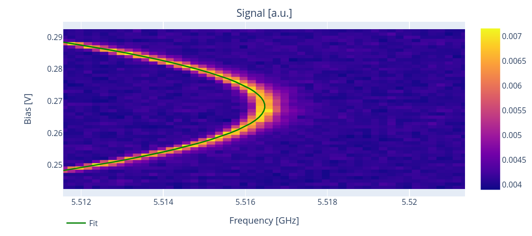
From the acquired data this protocol estimates the flux insensitive point “sweetspot”, which corresponds to the flux value where the frequency is maximed, as well as the drive frequency and the diagonal crosstalk coefficient \(V_{ii}\).
Note
From the cosinusoidal term in the transmon equation (1), it is clear that the sweetspot is not unique. In this protocol, Qibocal returns the sweetspot that is closest to the bias that is in the middle of the swept interval.
Both the sweetspot and the \(C_{ii}\) can be understood by writing the full expression for the flux felt by qubit \(i\) [1]:
where \(C_{ij}\) is known in the literature as the crosstalk matrix, while \(V_{i}\) is the applied voltage.
Requirements
Resonator flux dependence
Parameters
- class qibocal.protocols.flux_dependence.resonator_flux_dependence.ResonatorFluxParameters(*, freq_width: int, freq_step: int, bias_width: float, bias_step: float)[source]
ResonatorFlux runcard inputs.
- property bias_range: ndarray
- property frequency_range: ndarray
- freq_width: int
Width for frequency sweep relative to the readout frequency [Hz].
- freq_step: int
Frequency step for sweep [Hz].
- bias_width: float
Width for bias sweep [a.u.].
- bias_step: float
Bias step for sweep [a.u.].
- nshots: int
Number of executions on hardware.
- relaxation_time: float
Wait time for the qubit to decohere back to the ground state.
Example
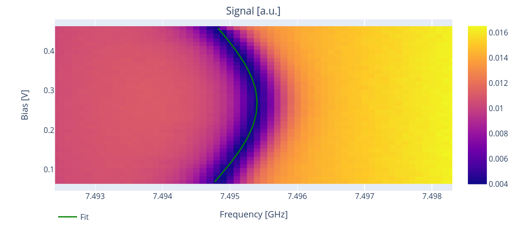
A possible runcard to assess how the resonator frequency changes by varying flux is the following:
- id: resonator flux dependence
  operation: resonator_flux
  parameters:
    bias_step: 0.01
    bias_width: 0.4
    freq_step: 100000
    freq_width: 6000000
    nshots: 2000
    relaxation_time: 1000